How Undersink Reverse Osmosis Units Work

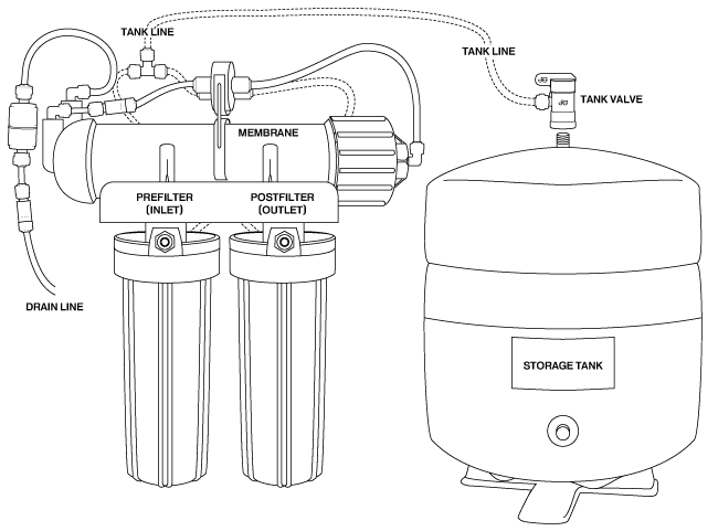
The drawing below is a standard 3-stage Pure Water Products Black and White undersink reverse osmosis unit. "Three stage" means that it has three main treatment devices--in this case, two carbon block filters and a reverse osmosis membrane.
Here's a step-by-step rundown of how it operates.
1. Pretreatment. Tap water taken from your cold water undersink faucet pipe enters the Prefilter (Inlet) port through the quick connect fitting just below the Prefilter (Inlet) label. The vertical prefilter canister contains a high quality carbon block filter which removes chlorine/chloramine and other miscellaneous chemicals. The filter protects the reverse osmosis membrane from disinfectants.
2. Shut-off system. Treated water exits the back of the prefilter canister via a 1/4" tube which loops its way to the top of the unit where it enters the Auto Shutoff valve. The Shutoff Valve is the round device clipped to the top of the horizontal membrane housing. In the Shutoff valve it makes a horseshoe turn and exits through the 1/4" tube that takes it to the right end of the Membrane housing. [More of the shutoff system and what it does later.]
3. The Membrane. The reverse osmosis membrane is contained in the horizontal housing labelled Membrane. Its function is to screen out hard to remove contaminants like fluoride, lead, arsenic, chromium, nitratesand others as well as make a 90% plus reduction in the "dissolved solids" like sodium in the water. The membrane separates the water it treats into two streams.
4. The Drain Water. One, called the brine or concentrate, contains the concentrated minerals and metals that are rejected. The reject water goes out the "drain line" at the extreme left of the unit. The drain line connects to a special clamp called a drain saddle that is installed on the undersink drain. The two cigar-shaped apendages in the drain line are a flow restrictor (above) and a check valve. The flow restrictor controls how much water flows to drain. It limits the drain flow to a tiny stream that is sized to suit the drain flow needs of the membrane. The other device, the check-valve, is a one-way valve. It allows water to flow toward the drain pipe but prevents it from flowing backward toward the ro membrane. Its function is to prevent backflow into the RO unit in the event of a blocked drain pipe. [Note: Most RO units do not have a drain line check valve and the flow restrictor is a much smaller part that is built into the fitting that connects the drain line to the membrane housing.]
5. The Product Water. The product water, the water you're going to drink, is often called "permeate." It leaves the left end of the membrane housing via the tube next to the drain line, passes through a check valve, and enters the left side of the Auto Shutoff valve. The function of the check valve is to keep back pressure from the unit's storage tank from pushing water backward into the membrane canister. This small check valve is essential for proper operation of the unit. [Instead of the external check valve in the picture, most RO makers use a tiny check valve that installs into the fitting at the point where the product water leaves the membrane canister.]
6. The Shut-off system revisited. As described above, the filtered tap water passes through the right side of the shutoff valve on its way to the membrane. On the other side of the shutoff valve, the permeate (product) water passes makes a horseshoe pass through the left side of the shutoff valve on its way to the Tank Line tee.
7. The Tank Tee. The tank tee serves as a fork in the road. Water takes the path of least resistance, and when it comes to the tank tee it goes to the pressure tank or to the inlet in back of the post filter. The tube that joins the tee and the storage tank serves as both entry to the tank and exit from it. Depending on where pressure is greatest, water flows into the storage tank or back toward the tank tee.
8. The Storage Tank. A storage tank is needed because the reverse osmosis membrane processes water slowly, at the rate of a fast drip or a tiny stream. The tank is pressurized with a light air charge. Water is collected in a flexible bladder inside the storage tank and is pushed out by air pressure when there is a demand for water.
9. The Post Filter. The final filter is connected to the dispensing spigot on the sink top with a single 1/4" tube that plugs into the the Post Filter (Outlet) fitting. The Post Filter is a high quality carbon block filter that removes any remaining chemical traces and polish the taste when water passes through it on its way to the spigot.
10. The Delivery and Shut-Off System. When the spigot on the sink is closed and the unit is making water, the product water has no place to go but into the storage tank. As the tank fills, it exerts increasing pressure on the left side of the shutoff valve. When pressure in the tank reaches about 2/3 the incoming water pressure on the right side of the shutoff valve, the pressure closes a piston that stops water from entering the unit. The unit remains off until a demand for water (opening the spigot) releases pressure on the left side of the shutoff valve. When the spigot is open water leaves the tank, goes through the tank tee, through the post filter, and out the spigot.